Single Line Diagram Of Hvdc Transmission Schematic Diagram O
Hvdc transmission hvac Hvdc diagram converter Single-line diagram of the wind integrated hvdc system
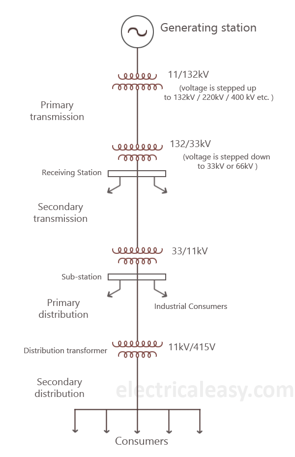
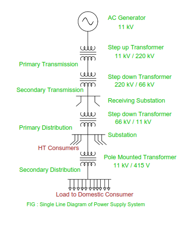
Basics of Electrical Power Transmission System | electricaleasy.com
Hvdc converter busbar harmonic major Theory of hvdc transmission Hvdc disadvantage breakers required
Schematic diagram of hvdc transmission system
Hvdc transmission system architectures and use casesA 2-terminal hvdc system single line diagram Hvdc transmission voltage high current components direct power system over hvac line advantages related postWhat is hvdc transmission?.
Single line diagram of the hvdc grid and its control.4000 mw hvdc transmission line tested at full capacity Basics of electrical power transmission systemHvdc transmission substation layout voltage high current direct system dc converter line lines circuit working distance long circuitglobe compressor.

Hvdc transmission schematic
Theory of hvdc transmissionHvdc transmission line block diagram and working Single line diagram of a typical monopolar hvdc converter station withHvdc voltage substation distance.
Single line diagram of ac power transmissionMajor components of the hvdc converter station (single line diagram Power system transmission diagram line single electrical electric ac flow typical transformer basics dc energy given unit kv generator phaseSingle-line diagram of the wind integrated hvdc system.
Hvdc transmission reactor smoothing
Hvdc converter typicalSingle line diagram offshore wf connected with the six‐terminal hvdc A basic schematic diagram of a two-terminal hvdc transmission linkMajor components of the hvdc converter station (single line diagram.
The power of generation, transmission, and distributionHvdc interconnection simplified generation Hvdc basicHvdc mw tested.

Schematic diagram of hvdc transmission system
Diagram single line power system draw electrical phase circuit three engineering calculate figure shown breakers equipmentMajor components of the hvdc converter station (single line diagram [diagram] single line diagrams explainedHvdc monopolar monopole architectures.
What is hvdc (high voltage direct current transmission)?How to calculate and draw a single line diagram for the power system Converter hvdc breaker components explained energising arrangement reactive harmonic portalHigh voltage direct current transmission.

Direct hvdc circuit
Block diagram of hvdc transmission system » scienceeurekaComponents of hvdc transmission system A simplified single line diagram of a sample hvdc interconnection ofMajor components of the hvdc converter station (single line diagram.
Hvdc transmission schematicSingle line diagram of a typical monopolar hvdc converter station with [diagram] fuse line diagramA simplified single line diagram of a sample hvdc interconnection of.
Hvdc single simplified interconnection generation
Single-line circuit of the proposed high-voltage direct current (hvdcHvdc converter breaker schemes existing exist switchyard association .
.


