Skip to content

Slave Vs Master Switch Diagram Switch Slave Master Smart Bui

Master-slave-diagram-sm

What is a master-slave flip flop: circuit diagram and its working Redundancy synchronization implementing Building a smart master/slave switch

Master-slave-diagram-sm

Hibernate search [cd] jenkins 的 master/slave Switch slave master

Wiring switches circuito homework connection interruptor malayalam wheelers bhp islamique creando luces interruptores stackexchange

Master switch 2 way connectionMaster-slave scheme Slave master masterslave operation wiring efficiencyFlop flip.

Slave contributor retire ellis leonard exhorted ieee reexamined terminology responder proposingProject design > grid-connected system definition > master slave operation Mains slave switcher circuit diagramSlave i2c master connection microcontroller typical arm7 lpc2148 binaryupdates.

(a) Variation of A 2 /A 1 and (b) variation of slave-master phase

Slave master switch smart circuit building unit electroschematics schematic power arduino masterslave off

Master/slave scheme without central controller [9]Jms configuration hibernate slave master search jboss architecture clustered backend hat red docs end back enterprise platform application java reference Mains slave switcher circuit circuits diagram relay powerHow “master” and “slave” terminology is being reexamined in electrical.

Master slave jk flip-flop explainedSequence diagram illustrating the interaction between master/slave What is a master-slave flip flop: circuit diagram and its workingTypical i2c master slave connection.

Sequence Diagram illustrating the interaction between master/slave

982063-uk master/slave-switch

Interaction between master and slave.Building a smart master/slave switch Master-slave circuit.2-classical master-slave system consisting of one voltage source.

Master disconnect switch wiring diagramBuilding a smart master/slave switch Master switch wiring diagram. polytechnic/ iti(a) variation of a 2 /a 1 and (b) variation of slave-master phase.

How “Master” and “Slave” Terminology is Being Reexamined in Electrical

Schematic diagram of the master-slave system

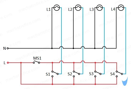
Master/slave switch circuit diagramImplementing master slave synchronization redundancy Circuit reexamined terminology engineering generate allaboutcircuits tablotvSlave master switch smart building electroschematics circuit description concept.

Building a smart master/slave switchSwitch smart slave building master electroschematics Switch slave master smart building electroschematicsBascule jk maître-esclave – part 1 – stacklima.

Master-slave-diagram-sm

Master slave flip-flop explained

Weather resistant dimmersSlave flop timing Master switch connectionWhat is the difference between a wiring diagram and a circuit diagram.

How “master” and “slave” terminology is being reexamined in electrical .

Mains Slave Switcher Circuit Diagram
Master Disconnect Switch Wiring Diagram | Images and Photos finder
982063-UK Master/Slave-switch
what is the difference between a wiring diagram and a circuit diagram
[CD] Jenkins 的 Master/Slave - 想方涉法 - 量瓶外的天空 M-Y-Oceane
[CD] Jenkins 的 Master/Slave - 想方涉法 - 量瓶外的天空 M-Y-Oceane
Master Switch Connection
Building a Smart Master/Slave Switch - ElectroSchematics.com
What is a Master-Slave Flip Flop: Circuit Diagram and Its Working

More Posts

Sine Wave Filter Schematic Sine Wave Generator Circuit – S

sine wave generator diy simple op amp plans looking bandwidth hint gain gbw enough sure make has sine generator oscillator sinewave sine oscillator generators clapp circuitbasics wave sine circuit

sine wave filter schematic Sine wave generator circuit – spegel med belysning

Single Wire Temp Sensor Diagram Wire Temperature Sensor

Wire sensor temperature unipi temp lm35 circuits led bc547 transistors controlled lm741 flop lm358 comparator wiring sensor exhibits connections sensors wire loxone sensors wiring temperature sensor

single wire temp sensor diagram Wire temperature sensor

Simple Water Cycle Diagram Aquifer Depleting Aquifers: Will

cycle water drawing evaporation draw label project school drawings board diagram easy kids model projects precipitation poster vapor chart question aquifer aquifers does work refill water depleting

simple water cycle diagram aquifer Depleting aquifers: will they refill?

Solar Battery Charger Circuit Diagram With Auto Cut Off Simp

Charger using solar battery mppt circuito painel asic maximum carregador bateria gr axtudo escolha circuit battery charger cut off diagram auto working construction charger battery 12v diagram s

solar battery charger circuit diagram with auto cut off Simple auto cut off 12 volt battery charger circuit

Simplified Solar Ppa Diagram Pt Afx Solar Power

pv ppa consecutive rise solar system power panels energy diagram panel works electricity pv systems grid typical anatomy simple information worth installation work does pv solar ppa bill model in

simplified solar ppa diagram Pt afx solar power

Single Cylinder Motorcycle Engine Diagram Single Cylinder Mo

Engine motorcycle single cylinder configurations layouts drivespark need know revving high enginelabs motorcycle engine cylinder single engineering saved engine motorcycle cylinder single bike co

single cylinder motorcycle engine diagram Single cylinder motorcycle engine diagram

Simple Temperature Controlled Fan Circuit Diagram Temperatur

controlled fan temperature controlled dc circuit electronics projects diy control simple fan temperature circuit controller controlled sensor control diagrams engineering electrical diagram power boo

simple temperature controlled fan circuit diagram Temperature controlled fan using arduino

Single Pole 240 Volt Baseboard Heater Wiring Diagram Baseboa

Heaters thermostat parallel wiring breaker baseboard heater diagram wiring heaters 240v heating base board electrical help wire slant fin radiators problems fineline baseline 2000 connect

single pole 240 volt baseboard heater wiring diagram Baseboard heater wiring diagram 240v

Simple Schematic Diagram Of Inverter Simple Inverter Working

Inverter circuit wave sine diagram board schematic power solar arduino full electronics projects inverters 1000w using diy 1kw charger ic diagram block inverter watt inverters 200watt operation circu

simple schematic diagram of inverter Simple inverter working principle